Flange Connection for Screw and Gearbox of Conical twin screw extruder
Conical twin-screw extruder: Pros and cons of the screw-to-reduction gearbox flange connection scheme
Conical twin-screw extruders (Conical Twin) typically feature two common types of drive end configurations:
① Rigid direct connection (Screw tail flange→ Output shaft flange; bolted fastening; no coupling);
② Reducer output shaft → elastic/drum-type gear coupling → screw rod.
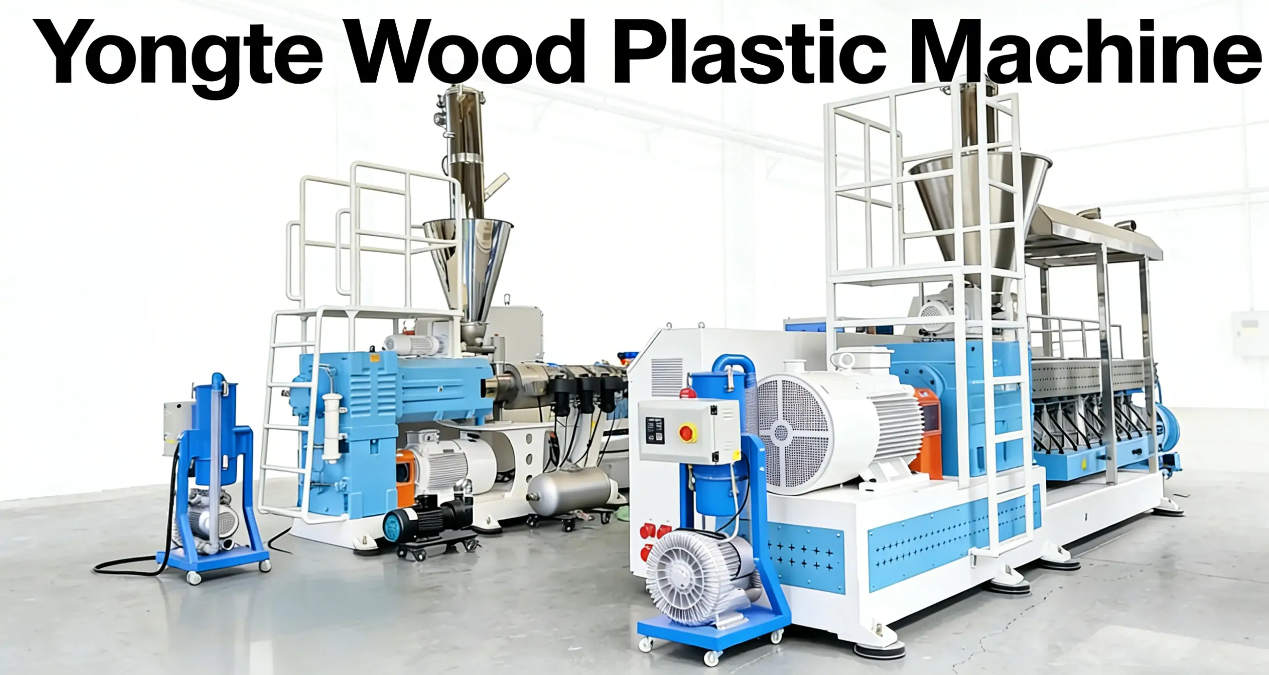
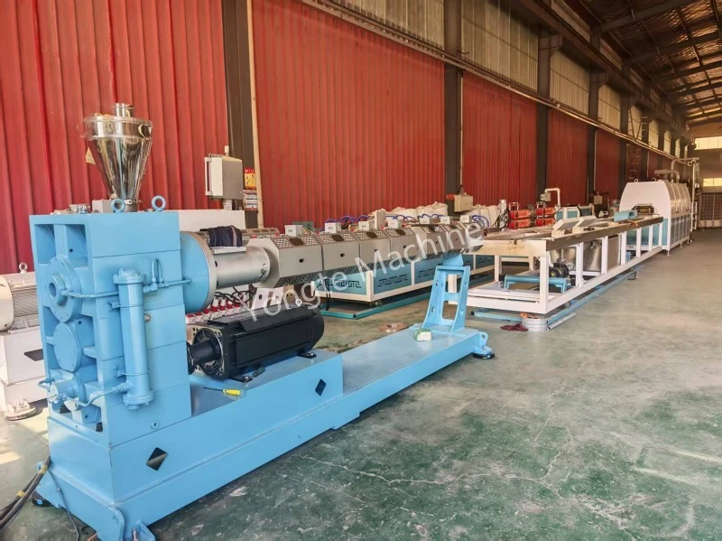
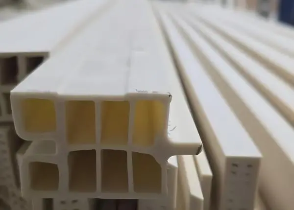
Yongte's conical twin-screw extruders typically employ an elastic coupling connection method; however, in response to a specific customer requirement, Yongte engineers have specially designed and manufactured a batch of conical twin-screw extruders featuring a flange-based rigid direct connection – these units are primarily used for the extrusion production of PVC window profiles. Actual production operations have demonstrated that, during high-speed continuous extrusion processes, the drive system operates with stable performance, and the screw's axial positioning accuracy meets the dimensional tolerance requirements for profile extrusion; furthermore, the appearance and mechanical properties of the extruded products fully comply with the customer's production standards. Compared to the coupling-based connection approach, this direct-connection configuration reduces the axial length of the drive shaft, saving space in the customer's workshop layout, while also eliminating the additional procurement and maintenance costs associated with coupling assemblies – making it perfectly suited to the customer's production needs as defined by their specific capacity planning.
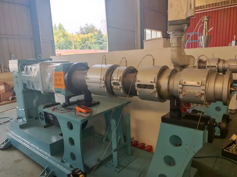
So, what are the advantages and disadvantages of the rigid direct connection method, and in which production scenarios is it suitable?
Advantages
1. The design is compact with short axial dimensions, eliminating the length required for an independent coupling; consequently, the overall machine body is shorter, reducing the equipment footprint. Given the limited inlet space of the conical double design, the shortened axial length facilitates the layout of the feeding seat and the vacuum exhaust port.
2. It features high torsional rigidity and minimal transmission clearance. Once the flange bolts are tightened, the connection becomes rigid, ensuring that torque transmission occurs without elastic buffer gaps. The two screws also exhibit superior synchronization, making this design particularly suitable for applications involving PVC powder—where screw clearance and meshing precision are critical—thereby reducing the risk of screw rubbing and material shearing fluctuations.
3. Simple alignment during installation, high torque transmission capacity; flange stop positioning ensures high centering precision; the flange surface can withstand substantial torque, providing ample load-bearing capacity for PVC processing applications involving conical double loading and high torque conditions. Compared to elastic couplings, this design eliminates the risk of rubber block aging and failure.
4. Few components and low maintenance costs – no wear parts such as coupling elastomers or gear sleeves, so coupling gaskets do not need to be replaced routinely; the lubrication system only requires maintenance on the reducer, with no additional lubrication points in between.
5. Excellent torsional stiffness and phase stability under impact loads: When subjected to feed rate fluctuations or transient load impacts, the phase difference between the two screws remains minimal, preventing screw meshing interference and making this configuration ideal for continuous, stable extrusion operations.
shortcoming
1. Lacking buffer damping capability, all impact loads are transmitted directly; load fluctuations and start/stop shocks are transmitted directly to the reducer's bearings and gears. Should the screw become jammed or trapped by material, the impact load acts directly on the reducer's output shaft, which can easily damage the gears or the output bearings; therefore, stringent overload protection measures are required.
Comparison: The elastic coupling can absorb part of the impact, thereby protecting the reducer.
2.
3. Extremely stringent coaxiality (centering) requirements: In the case of a rigid flange connection, inadequate cleaning of the joint interface during installation, uneven bolt loading, or foundation settlement may cause coaxiality deviations. These conditions can generate additional bending moments during operation, leading to: fatigue fracture of flange bolts, bending of the reducer output shaft, or rapid wear of the bearing at the tail end of the screw.
4. Thermal deformation cannot be compensated for: after the conical double cylinders are heated, the screw elongates; however, the flanges remain rigidly locked, preventing the release of axial thermal expansion.
· Consequences: The end of the screw is subjected to significant axial thrust, causing the thrust bearing load to surge, leading to bearing overheating and reduced service life; in severe cases, this may push the screw toward the head end of the machine, thereby altering the screw clearance within the barrel.
This represents the most critical pain point associated with the direct connection using conical double screw flange; many machine models are equipped with a thrust bearing assembly specifically designed to absorb axial thermal expansion.
5. Complex disassembly and assembly process: When replacing the screws or cleaning the cylinder, all flange bolts must be removed, and the screws are "rigidly coupled" to the output shaft of the reducer; therefore, when extracting the screws, the positioning of the reducer end must also be considered, making the disassembly and assembly procedures time-consuming. Additionally, the flange shoulder is susceptible to impact damage; once this shoulder is damaged, the centering precision will be compromised, rendering the equipment inoperable.
6. Fault propagation: Damage to one component indirectly affects another component – a stuck screw → the impact is transmitted directly to the reducer; deformation of the reducer's output shaft → directly causes the screw to deviate, leading to the screw scraping against the cylinder, thereby amplifying the fault through a chain reaction.
Use Cases & Selection Summary
✅ Suitable for: PVC profiles and PVC pelletizing; stable operating conditions; uniform material feeding; reliable system integration; and conical double bearings equipped with overload protection and high-power thrust bearing sets.
❌ Not suitable for: conditions involving frequent material blockage, frequent start-stop operations, or highly fluctuating loads; without reliable torque limiting protection, the failure rate of flange-directly coupled gear reducers will increase significantly.
Engineering improvement approaches (commonly implemented by many cone double manufacturers)
1. The flange surface utilizes a positioning keyway combined with high-strength hinged-hole bolts to ensure proper centering;
2. The reducer's output shaft is equipped with a high-capacity thrust bearing designed specifically to withstand the thrust force generated by the axial thermal expansion of the screw shaft;
3. Add a torque limiter (shear pin/frictional torque protector) to instantly cut off torque during material blockage, thereby protecting the reducer;
Perform regular re-inspections of the flatness and coaxiality of the Flan-Means; tighten the bolts in diagonal stages, ensuring the preload is properly controlled.
Related News
- Advantages of Rubber Soaker Irrigation Pipes vs Traditional Irrigation Tubes
- Can Yongte Supply Turnkey Project Service for WPC decking plant?
- 200x50mm Recycled Solid Plastic Lumber Machine Tested Successfully
- Yongte WPC Column making machine with co-extrusion is successfully tested
- How can plastic film wastage be used to produce wood-plastic composite (WPC) products?
- WPC Extrusion Machine Temperature Setting
Leave me a message