Disassembly and Assembly Parallel Double Screw for WPC Pelletizing Machine
SH75 Parallel Double-Screw Disassembly and Assembly Guide
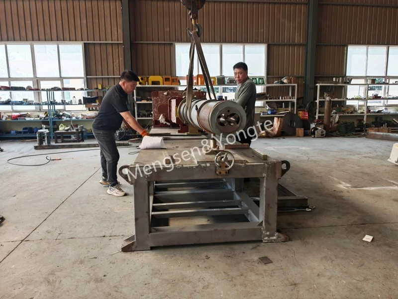
During the operation of the WPC pelletizing machine, if maintenance is required due to wear and tear on the screw and cylinder assembly, the user shall disassemble and reassemble these components. The disassembly and assembly procedures for the SH75 modular flat twin-screw machine must be carried out in strict accordance with the prescribed operating procedures; all personnel involved in these operations should familiarize themselves with the operating specifications in advance and take appropriate protective measures to prevent safety accidents or equipment damage resulting from improper operation. The flat twin-screw machine disassembly and assembly guide provided by the Yongte engineering team is intended solely as a reference for operators.
Applicable to: Yongte WPC Pelletizing SH75 Parallel Double-Screw Extruder – Building-block-style parallel double-screw threaded components (conveying blocks, kneading blocks, shearing blocks). These components must be operated in pairs with the left and right screws properly phased to ensure the correct phase relationship between the two screws during assembly, thereby preventing component interference or abnormal equipment operation caused by phase deviation.
Before starting any operation, the LOTO (Lockout/Tagout) procedure must be strictly followed: all power sources must be disconnected and it must be confirmed that the equipment is completely shut down to prevent personal injury or equipment damage caused by accidental startup.
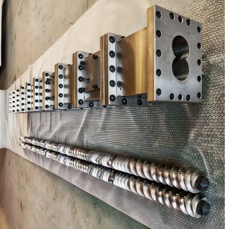
1, Preparation
1. Tools and Consumables
· Special-purpose screw extraction tool, hydraulic pulling device/press, copper rod, copper shovel, copper wire brush, wooden hammer (direct striking of the threaded block work surface with a steel hammer is prohibited)
· Torque wrench, hex key, high-temperature anti-sticking grease (molybdenum disulfide high-temperature lubricating grease), marker pen, high-temperature resistant gloves, clean wooden block / rubber pad
· Cleaning agent, compressed air, protective goggles
2. Shutdown Pre-Operation (Before the screw is withdrawn from the barrel)
1. Before shutting down the machine, thoroughly clean it using the cleaning agent and try to drain all material from the tank.
2. Cool down to a safe temperature; disconnect power supply, place a warning sign and lock the area; turn off heating, feeding, and vacuum systems.
3. Remove the machine head die, multi-hole plate, heating coil, thermocouple, vacuum cover plate, and feeding port.
4. Loosen the segmented flange bolts on the screw barrel; prepare to extract the entire twin-screw assembly.
2, Full screw withdrawal (pre-process)
1. Disconnect the output-end coupling of the reduction gearbox; mark the phase of the left and right screws and the spline (this is critical to prevent incorrect installation phase from damaging components).
2. Operating / Hydraulic fixture: horizontally synchronize the withdrawal of two screws; ensure both screws remain in parallel engagement – do not pull them forcefully on one side.
3. Place it on a wooden block; keep the screw suspended so that it does not come into direct contact with the ground, which could damage the thread profile.
4. Clean materials while they are still hot: use a copper shovel and copper brush to remove carbides; if the material becomes stuck between the threaded block and the mandrel, apply localized, uniform heating to soften the material before disassembling; it is strictly prohibited to subject the component to intense localized heating.
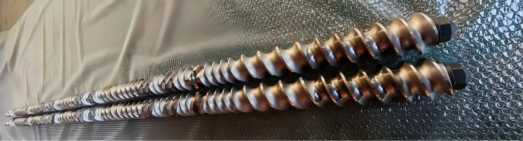
3, Threaded block (component) disassembly procedure (disassemble sequentially from the machine head toward the reduction gearbox end)
Sequence: Front locking nut → Radial retaining ring → Each set of threaded components
1. Loosen the front locking nut (it is usually threaded internally – do not reverse the thread direction); then remove the locking nut, the thrust washer, and the positioning ring.
2. Remove the threaded blocks group by group, then remove the paired A/B screw components from the same position; mark each group of components with a marker pen – indicating the position number + side (front/back) + screw orientation (left/right); take a photograph to document the assembly sequence diagram.
3. Threaded block stuck on the mandrel: Use a hydraulic press combined with specialized tooling for axial pressing, with the assistance of a copper rod; it is strictly prohibited to strike or pry the threaded surface at an angle; it is also strictly prohibited to directly heat the component's working surface using an oxyacetylene torch.
4. After complete disassembly: clean the core pin spline, the outer diameter of the core pin, and the internal spline groove of the component; remove any accumulated carbon deposits or hardened material; inspect the spline for wear, cracks, or chipping.
5. Component inspection: Check for wear on thread profiles and engagement surfaces, as well as for pitting or cracks; components with excessive wear shall be immediately scrapped; grinding or repair is prohibited; such components must not be reloaded into the machine.

4, Threaded block assembly (assemble in reverse according to the original drawings or markings, from the gearbox end toward the machine head end)
1. Clean the core mandrel spline and the component's internal spline; apply a thin layer of high-temperature anti-sticking grease (do not apply a thick layer to prevent carbonized material buildup during production).
2. Fit the threaded blocks sequentially according to the marking order; install them in pairs, ensuring that the engagement phases of the A and B screws are aligned; ensure that the component end faces are tightly pressed against each other with no clearance, and that the spline is fully seated in place.
The conveying block, kneading block, and shearing block have a specified orientation and must not be installed in the reverse direction; the rotation direction and angle of the kneading block must strictly comply with the process drawings.
For each set installed, manually turn the two screws to ensure smooth engagement with no jamming or scraping.
3. Install the positioning ring and the thrust washer in sequence, then tighten the front-end locking nut.
4. Tighten the locking nut to the specified torque (75 Nm; generally refer to the manufacturer's recommended torque; apply diagonal pre-tightening in 2–3 separate steps – do not tighten it all at once).
5. After assembly is complete, manually adjust the two screws: ensure smooth, continuous rotation without any jamming or abnormal knocking sounds; there should be no metal friction between the two screws.
6. Verification: Compare with the original assembly photos to verify the component sequence, orientation, and quantity.
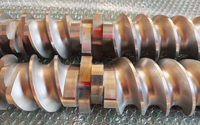
5, Screw reassembly of the barrel
1. Clean the barrel interior thoroughly; ensure the bushing is free of carbonized material and inspect the bushing for wear.
2. The two screws remain meshed with constant phase; when the barrel is horizontally synchronizedly pushed in, the resistance is immediately detected and the machine should not be operated under excessive force.
3. Mount the rear coupling, align it with the previously marked spline phase, and secure the connecting sleeve and positioning pin.
4. Reinstall the barrel flanges for each section and tighten the flange bolts in diagonal stages.
5. Restoration heating coil, thermocouple, vacuum port, feeding section, machine head die
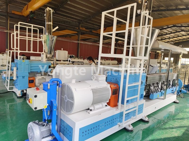
6, Test Run Inspection
1. Restore all wiring connections, disengage the LOTO, manually rotate the shaft at low speed for a few turns, and confirm that there are no abnormal friction noises.
2. Perform a no-load, low-speed jogging test, monitoring current and vibration; if no abnormalities are detected, increase the temperature; after the temperature is raised, perform another turntable test for re-inspection (as equipment may tend to jam due to thermal expansion).
3. Conduct trial production with low-speed feeding; monitor torque and pressure fluctuations; confirm no abnormalities.
7. Key Risks and Contraindications (75 Dual High-Frequency Fault Points)
1. ❌ It is prohibited to strike the threaded block work surface with a steel hammer; doing so may cause edge chipping or loss of the alloy layer, resulting in immediate scrapping.
2. ❌ Incorrect phase installation leading to forced motor rotation: Directly disengaging the clamping block or scratching the barrel bushing.
3. ❌ If carbon deposits or iron filings are present on the threaded block's end surface before assembly → this may cause surface damage or component binding, making the component impossible to remove during the next disassembly cycle.
4. ❌ Excessive or insufficient locking nut torque: Insufficient torque may cause components to shift or break; excessive torque may lead to the nut becoming stuck during the next disassembly process.
5. ❌ Unilateral withdrawal of the screw causes misalignment between the two screws and component collisions.
6. ✅ Take photos and mark components during disassembly – this is especially important for assemblies consisting of multiple interlocking blocks, as it is very easy to misalign the sequence or angle based solely on memory.
Related News
- Large Parallel Twin-Screw Plastic Recycling Extruders for African Client Under Production
- Yongte plastic recycling extruder running in Africa
- How many molds are needed for one set of door frames?
- Integrated Anti-Bridging Feeding System for Recycled Plastic Extrusion
- Yongte Rubber Foam Microporous Seepage Pipe Production Line Successfully Commissioned for Indian Client
- Advantages of Rubber Soaker Irrigation Pipes vs Traditional Irrigation Tubes
Leave me a message