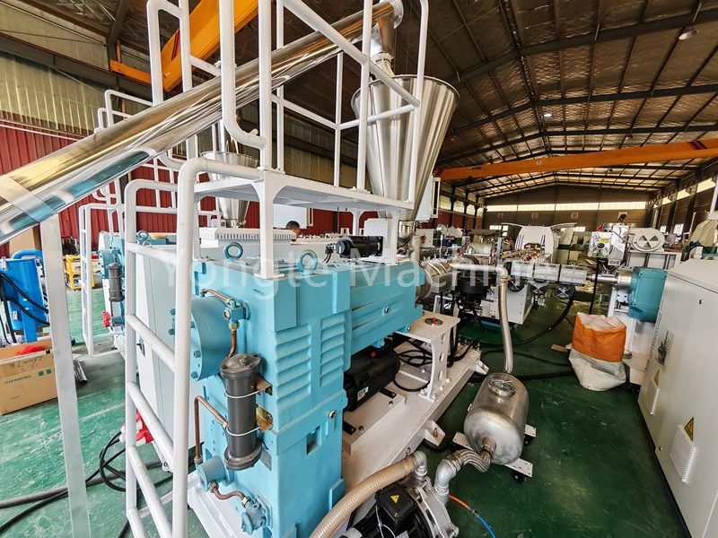
Screw spacing adjustment for SJSZ65/132 WPC door frame conical double screw extruder
SJSZ65/132 PVC-WPC (Wood-Plastic Composite) Door Frame Conical Double-Screw Extruder
Special Adjustment Plan for Screw Spacing (Yongte Equipment – On-site Implementation Version)
For PVC wood-plastic composites (characterized by high wood powder content, high filler ratio, susceptibility to wear, and ease of charring of wood fibers), the clearance between parts cannot be simply adopted from standard PVC profiles; instead, a slightly larger clearance is required for wood-plastic composites to reduce friction heat, minimize screw wear, and prevent the wood powder from burning.
- Model: SJSZ65/132;
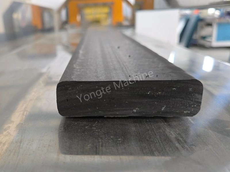
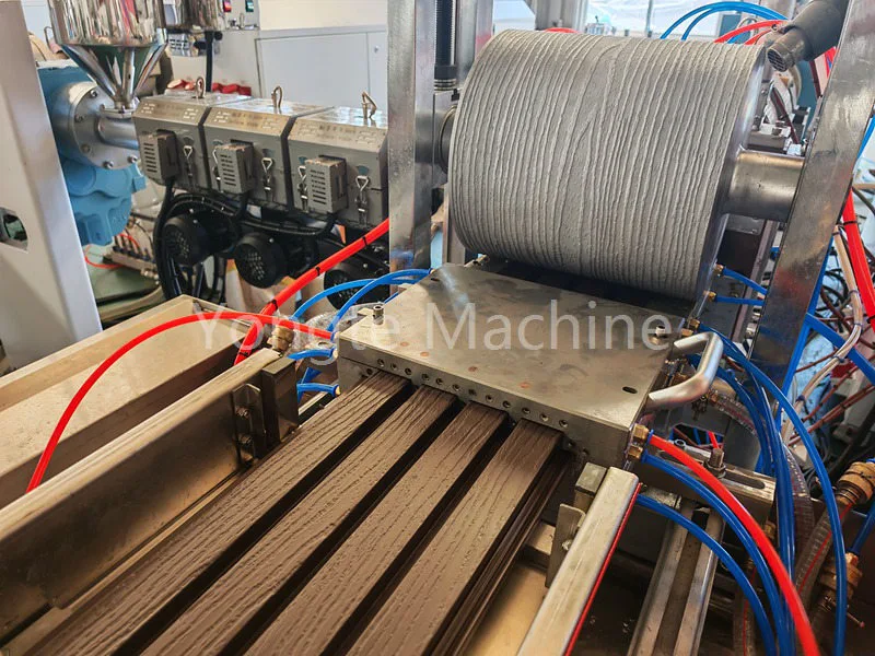
- Applicable products: PVC wood-plastic solid door frames / door surrounds;
- Adjustment conditions: under normal ambient temperature in the cold state of the entire machine, after power loss and shutdown, or after clearing residual materials from the machine barrel.
- Adjustment principle: The axial position of the screw is adjusted by using a thrust copper gasket at the rear end of the screw ✅ Thickening the gasket → the screw moves forward (towards the machine head) → the clearance decreases ✅ Thinning the gasket → the screw moves backward (towards the distribution box) → the clearance increases
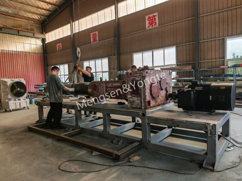
1、Target reference parameters (cold-state measurement standards)
1. Screw retraction reference stroke (Recommended: 7.0 mm)
Range: 6.5–7.5 mm (commonly used for standard PVC profiles: 6–7 mm; the upper limit for wood-plastic composites is relaxed).
Taper conversion: For the SJSZ65/132 model, for every 1 mm axial displacement of the screw, the unilateral radial clearance between the screw thread and the barrel changes by ≈0.022 mm.
2. Three types of gap control indicators
table
|
Gap Type |
Cold-state single-sided standard interval |
Key Specifications (MPS Exclusive) |
|
Helical ridge ↔ radial clearance between the barrel inner wall |
0.28~0.35 mm |
Perform multi-point measurements at the feeding large end, middle section, and discharge small end; the wood-plastic mixture must not contain particles smaller than 0.25 mm to prevent abrasion of the screw rod and localized overheating or carbonization of the wood powder. |
|
Meshing side clearance between two screws (screw threads – opposite grooves) |
0.12~0.20 mm |
The gap difference between the left and right sides shall be ≤0.06 mm; single-sided tight-fitting friction is strictly prohibited. |
|
Threaded shank end face ↔ Convergence core axial clearance |
3.5~4.5 mm |
Prioritize selecting 4 mm; if the clearance is too small, end-face friction may cause overheating; if the clearance is too large, material may become trapped, leading to black streaks on the door frame surface. |
⚠ Wear Warning: After prolonged operation, if the radial unilateral clearance exceeds 0.40 mm, the screw must be repaired; this will result in increased backflow, uneven plasticization, air pockets appearing in the door frame, and a rough surface finish.
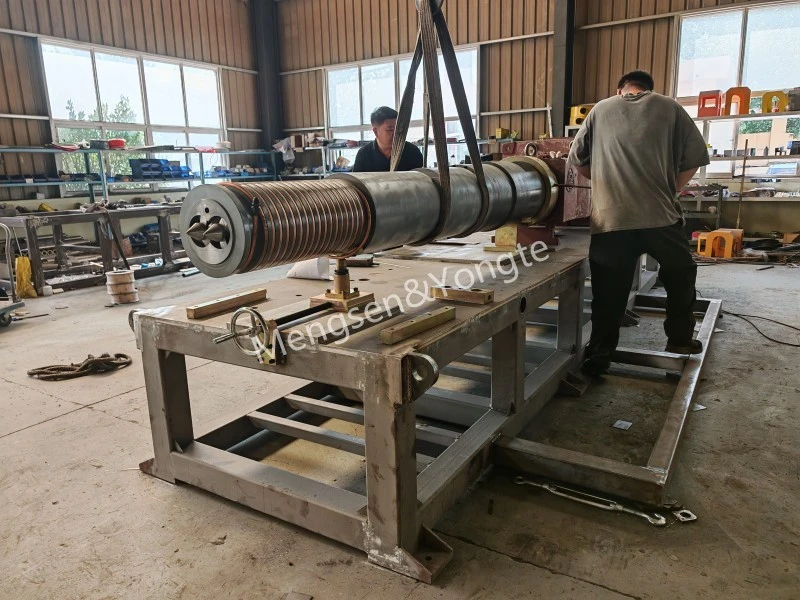
2、Prepare tools
Magnetic dial indicator + mounting base, 0.02 precision feeler gauge, depth micrometer, complete set of purple copper adjustment washers (0.05/0.10/0.20/0.5 mm), pure copper rod (striking steel rods on screws is prohibited), marker pen, high-intensity flashlight.
3、Standardized adjustment steps (strict sequence; order cannot be reversed)
Step 1: Assembly pre-inspection and coaxiality check
1. Clean the screw, barrel, and mixing core; inspect the screw ribs for any scratches, burrs, or carbonized deposits;
2. Install two screws; align the spline with the output shaft of the distribution box, then insert the spline-connected sliding sleeve;
3. Manually crank the unit for at least 3 full revolutions; throughout the process, there shall be no severe jamming or any abnormal metallic friction noise;
4. Verify that the barrel support is level, and that the alignment deviation between the barrel and the distribution box is ≤ 0.05 mm.
If the turning gear exhibits periodic abnormal noises, first resolve the alignment issue; do not make blind adjustments to the gaskets.
Step 2: Measure the maximum axial play of the screw shaft (using a dial indicator method)
1. The magnetic force gauge base is fixed at the front end of the barrel; the measuring tip rests on the end face of the screw's small head, and the dial is set to zero;
2. Use a copper rod to fully tighten the screw until it reaches the rear dead center (near the distribution box), where it will remain stationary;
3. Use another screw to push it forward until it reaches the limit position; read the value = total stroke displacement of a single screw;
4. The left and right screws are measured independently; rotate each by 180° and perform two replicate measurements, then record the data.
Step 3: Adjust the Thread–Cylinder Radial Clearance (adjust first).
Objective: The screw retraction stroke shall be stabilized at approximately 7.0 mm, and the radial clearance shall fall within the range of 0.28–0.35 mm.
1. Add or remove brass gaskets at the thrust shaft end face of the screw;
2. After completing the coarse adjustment, insert a feeler gauge from the feeding port and measure at three points: ① the feeding section (at the large end of the screw rod, end 132); ② the middle section of the barrel; ③ the discharge small end (at end 65).
3. The peripheral clearance must be uniform; the feeding section is most prone to cylinder scraping, requiring close inspection!
MDF production guidelines: It is better to allow a margin slightly above the upper limit than to adhere strictly to the lower limit, as this helps reduce grinding heat.
Step 4: Adjust the Double-screw meshing side clearance (Core)
1. Fix the position of screw A in place; then, pry screw B forward and backward, and record the forward and backward extreme positions;
2. Observe the clearance on both left and right sides of the two screws' meshing pair to ensure that the clearances on both sides are essentially equal;
3. The clearance between both sides is uneven: only a minor adjustment of 0.05–0.1 mm via gasket fine-tuning is permitted; significant modifications are prohibited; ✅ Acceptance criteria: at any rotation angle of the screw rod, there shall be no mutual scraping between the screw ribs, and the difference in clearance between both sides shall be <0.06 mm.
Step 5: Verify the Threaded shank-to-confluence core end-face clearance
Two screws simultaneously add or remove identical thickness gaskets, moving them uniformly forward and backward to adjust the end face distance to 3.5–4.5 mm.
Adjusting a single gasket individually will compromise the meshing clearance!
Step 6: Locking, marking, and no-load verification
1. Once the clearance meets the specified requirements, uniformly tighten the rear clamping nut;
2. Mark alignment reference marks on the screw, spline sleeve, and output shaft; when disassembling and reassembling in the next cycle, simply restore the original alignment using these reference marks;
3. Room-temperature, low-speed manual continuous turning for 5 full revolutions; Acceptance criteria: ✔ No sharp metal friction noise throughout the entire process; ✔ The rotational resistance is uniform, with no periodic sticking points;
4. For new machines or overhauled screw drives: perform a 30-minute low-speed no-load warm-up period, and continuously monitor for any abnormal noises.
4、The impact of gap size on the production of PVC wood-plastic door frames
① Gap is too small (below the lower limit)
· The screw scrubbing mechanism and the twin-screw mutual grinding process cause the frictional heat to rise sharply;
· During high-temperature carbonization of wood powder, black lines and charred particles appear on the surface of the profile;
· The motor torque surges, exacerbating wear on the duplex screw and increasing the load on the thrust bearing.
② Gap is too large (exceeds upper limit of 0.35 mm)
· The reverse melt reflux is intensified, resulting in uneven plasticization;
· Output fluctuation is significant, the door frame wall thickness is unstable, and micro-pores appear inside;
· Significant pressure fluctuations, difficulty in shaping, and decreased production output.
5、Wood-Plastic Composite Applications: Specific Contraindications and O&M Key Points
1. ❌ Prohibit temperature increase during hot-state adjustment: PVC and wood-plastic composite materials operate at high temperatures; due to metal thermal expansion, if the gap is adjusted in the cold state but then increased in temperature, cylinder rubbing may easily occur;
2. ❌ Do not use iron gaskets; copper gaskets must be used to absorb impact and protect the thrust face;
3. ❌Once adjustments are complete, proceed directly to full-load production; it is recommended to perform a transition phase using low feed rates, low speeds, and no-load preheating.
4. The PVC-wood composite formulation utilizes wood powder and calcium carbonate as fillers, constituting a highly wear-prone system: the wear amount of the screw rib shall be measured every 4,000 hours; if the unilateral clearance exceeds 0.4 mm, spray repair shall be performed;
5. If there is material leakage in the vacuum exhaust section or if the pressure remains unstable, prioritize checking whether the clearance exceeds the specified limits;
6. If the wood powder addition ratio exceeds 55%, the reference backlash travel can be set between 7.2–7.5 mm (with the clearance appropriately increased).
6、On-site simplified startup diagnostic procedure (when disassembling the unit for measurement is inconvenient)
Raise the temperature to the wood-plastic processing range of 165–175 °C; operate the main unit at low speed in point-to-point mode under no-load conditions:
1. Periodic sharp metallic friction noise → indicates a too-small clearance; uniformly increase the gasket thickness;
2. Low torque, erratic discharge speed (sometimes too fast, sometimes too slow), multi-porosity in the door frame cross-section, and dry plasticizing → the clearance is excessive; make a slight forward fine adjustment;
3. During stable production, irregular blackened spots continue to appear; first, verify whether the gap is too small, which may cause localized overheating.
Related News
- Advantages of Rubber Soaker Irrigation Pipes vs Traditional Irrigation Tubes
- Can Yongte Supply Turnkey Project Service for WPC decking plant?
- 200x50mm Recycled Solid Plastic Lumber Machine Tested Successfully
- Yongte WPC Column making machine with co-extrusion is successfully tested
- How can plastic film wastage be used to produce wood-plastic composite (WPC) products?
- WPC Extrusion Machine Temperature Setting
Leave me a message